Friday 28 October 2011

Story Board

Here is my basic story board for my short film.


From the top Left.


The lights count down and go green,


Anakin and another pod race from the line neck and neck.


As they pass under a rock archway the other pod smashes in to Anakin but during the contact pushes himself to the right and then in the next scene you see him heading towards a rock wall as the gap closes.


next you see it crash.


And the final scene is a surprise. 

Thursday 27 October 2011

Pod racing video

Below is the scene from Starwars Episode one that has inspired my assignment sequence.

Creating Terrain

As part of my scene the pod race will take part in the desert and mountains of Naboo so for this to happen I will need to create some terrain for the race to happen within.


I decided to do some research and have combined several differant things I learnt from various tutorials and some youtube videos to create the following steps. 


Firstly you have to draw out a large plane or to the scale you require.


Then in the parameters increase the amount of segments in this case because of the size of the plane I have gone for 400 x 400 unfortunately this gives 160,000 segments which is not ideal but further experimentation with this technique will hopefully help me get this figure down in the final film.


The next step is to apply the displace modifier to the plane this is what will do the magic later on.

Next step out of 3Dmax and head for your browser & google to search for height maps, once this is done you will see many types of terrain in a form not dissimilar to an X-ray.

After this you then look for the image section of the displace tool bar and where it says none click there and then select and add the image you have just acquired. 


 Once you have imported the next stage is to increace the strength and as you increase it as if by magic your terrain starts to rise from the plane.

Below is the final terrain image its at this point that you can see why I added so many segments at the beginning ultimately the more segments you have the more detailed your terrain is but that may come at a performance cost later on.
Once this is complete you can apply a texture and its done.

A bit of a problem....

During the UVW map modifier tutorial I encountered a problem I managed to set everything up with the correct modifier etc but could not find where to add the image to then trace it on to the component. 
I tried many different ways including trying to go through the materials panel but just couldn't crack it.  


Map Channels

In the previous tutorial & example I applied a texture to there diffuse channel but there are more channels that can be used to apply textures to objects. 


If these channels are used well it is possible to recreate something like human skin where you have multiple layers like skin flesh veins and muscle.


To access the extra channels you simply have to drop the maps section down in the materials control panel.

Applying Materials

To begin applying materials to your objects you first have to open the materials editor this can be done by selecting it from the tool bar or pressing the M key.

Then from the menu at the top select modes and then the compact editor mode.

To make my metal object I drew a sphere and then applied the metal shader to help with the metal effect and then adjusted the specular and glossiness variables to give it a nice metallic shine. 


To create the wood texture I made a sphere and then made it brown. I wanted to use the proper wood effect on the sphere but I was having problems applying it to the object.
To make it react a bit more like wood I reduced the specular and glossiness levels down because if wood is not varnished it does not reflect much light.


The next step was to begin applying the floor texture to different objects. It was at this point that I realised what I had been doing wrong when I wanted to apply my wood texture. Rather than just selecting the texture through the top tool bar beneath the sample images I should have added it with the specular button.
You can see in the image below that in the top right hand corner example on the materials editor the texture is flat but on the one next to it the texture is wrapped around the sample.

I then proceeded to add textures to all the different shapes requested on the work sheet. It fitted some better than others because such a geometric pattern doesn't work well with something that has an organic shape like the teapot.

Now I had released and understood what I was doing wrong when I wanted to apply a more realistic wood effect to my sphere in the first task i went back and re did with the material I wanted. 

The next step was to add some different materials to planes, After doing this it was clear to see that some of these may be very useful in my final project. 


Below are examples of the following procedural maps


CELLULAR
DENT
MARBLE
NOISE
PERLIN MARBLE
SMOKE
SPLAT
WAVES 


I also did an extra plane with vector colour because I was interested in how it would look. 

Skeches

Below are some sketches I did of 2 pod racers One of them I went on to recreate in 3D max


I felt by scotching them I would get a better feel for them and understand the flow of the shapes which could only be a good thing.   


Wednesday 26 October 2011

Ferrari does PodRacing

For my final model I wanted to get away from the standard Starwars Pods and make something from my own imagination. The model I designed was forged from the idea of a futuristic formula one car.
The main chassis was formed in the same way as my previous 2 models.
I also added a spoiler to the rear by extruding polygons and then reshaping so that the struts were aero dynamic and created a wing from a very thin box which I then adjusted a vertex on to give it a sharp edge. 

The next thing to do was create the engines once I had the shape I wanted I then considered where to add some air intake vents my first thought was in the middle but in practice this would not look very good.

In the end I decided to go for dual air vents on the engines via a boolean operation.   

I then added a row of spikes to the top to add some detail and make them look a little more aggressive.

Below are 2 images of my final model. 

Second PodRacer Model...

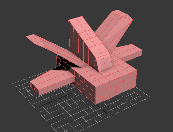
For my next model I started by once again drawing a box but this time after making the shape an editable poly I used the extrude polygon tool to drag out the extra detailing.
I then played with the levels of the extruded polygons and also tweaked different vertices to get slopes and nice clean edges.
Later on I used the bolean tool to cut out the vents from the engine side pods.

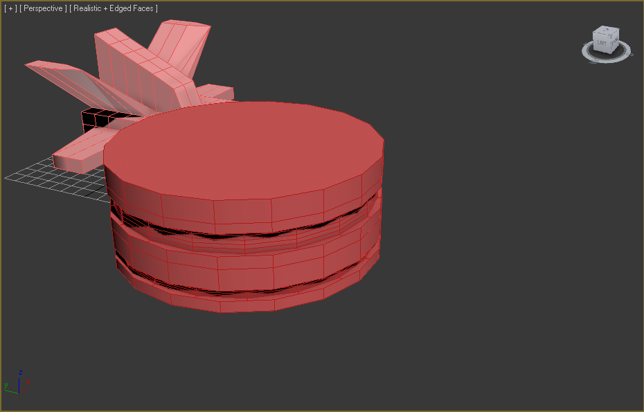
I then had to produce the front engine sections these are large circular fan like modules, so to start off I drew a cylinder and then used the tube shape and positioned it with the align tool to cut out sections with my old friend the boolean tool.

Below is the finished product from that process. 

The next step was to once again cut out a section from the existing cylinder and then add a pivot for the fan blades. 

I then added a tube section and created 8 fan blades which I then attached to the tube to finish off the engine.
This was then rotated and attached to the front of the previously created engine component.  

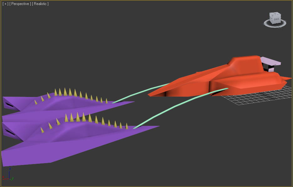
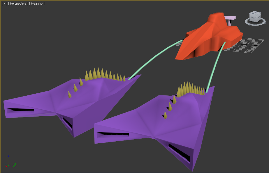
After this I created a mounting rack and side pods for the rear capsule.

I then created some couplers on the rear of the engines to attach the hoses to from the main pod.  

I then added some connecting hoses. 

Below are two images of my completed pod


One thing I realised quite late in the process of building my engines was that I had not used enough segments in the creation of the circular fan housing's. This has lead to a slightly bumpy effect that can be seen in the image above. Unfortunately this can't be corrected because once boolean cutting has been applied you can't add more segments or make the object an editable poly again.  

Anakin's Podracer....

For my first model I wanted to recreate Anakin's pod racer from Star-wars Episode 1. For aloof at the original please see previous blog posts.

I started by beginning with the engines. I started to create one and then I would clone that once it was finished.
First of all I started by drawing a cylinder and a cone and then used the align tool to bring them together perfectly. 

I then adjusted the diameter of the cone to get it right. 

The next stage was to start shaping the engine casing in the pictures I was working from the casing gradually got wider in 3 steps.
To recreate this I created a tube adjusted it to cut the casing exactly as I wanted and used the boolean tool to then remove the section. 

I then repeated the previous process but with a bigger inner diameter further up the casing which gave the result below.

The next step was to round off and shape the area of the casing just before the cone. This was once again done using boolean in what was quite honestly in hindsight a over complicated way.
First I created another tube and then used boolean to cut out a cone from that so it had a inner sloping edge. 

I then used the newly created shape to then cut away from the engine to give a nice rippled slope like a jet booster. 


 My next task was to create the enclosure for Anakin this was done by drawing a box and then working on it at the polygon and vertex level.  I spent a long time playing with the shape which the screen shots don't really reflect.
One problem I had was some of the polygons not sitting properly and affecting the quality of the shape. while I was having these issues I came across the collapse polygon feature which helped a lot and using this seemed to reduce the polygon count as swell.
Once I had the shape I wanted I then applied the mesh smooth modifier which grated the nice shape seen in later posts.    

The next step was to create the scoops for the front of the engine this was done in the same way as the cockpit but with smaller boxes.
I was also able to create the flick up vent at the rear by lifting a vertex and removing the polygons. I was able to do this because the scoop will be in contact with the engine at the point where the polygons were removed so there will be no issues with texturing etc.

Positioning of the scoop using the align tool.

Rotation of the other scoops by eye using the dialog box you get if you right click on the rotate button. I then used the rotation amount from one bottom scoop to position the other.

 I then created a windscreen for the pod by creating a sphere and then breaking it apart by doing this I was able to get a sort of broken glass effect and attempt to show some of the ware and tare Anakin's pod has in the films. 
After this I applied a translucent material to the windscreen and adjusted its reflectivity.

Next I created a bar and mounting point for the connections from the pod to the engines.


I then drew a cylinder and rotated it to be on a flat axis with the pod and engines. After this I then applied the bend modifier to add the curve you see below. I then positioned using rotate and move to get it just right. 

I wanted to ad a different shape to the connections so that they loop up and down to the engines I tried to do this using the slice tool to ad more flex points but I was unable to get this right. 

Once I had completed my model I then went to wire frame mode and turned on the polygon counter located under the tools section of the right hand tool bar.
Here it was noticed that I could have been much more efficient with my polygons on the engines. When I had created the model I used too many segments down the length of the cylinder which were not needed because I was using boolean to shape it. 

Below are 2 images of my completed Anakin Skywalker PodRacer