With the skills learnt through the worksheet I had a play with splines and the lathe tool.
Firstly from the right hand tool bar I selected the 2d shapes and splines section and then drew out a circle.
From here I then removed some points in the circle to grate a flatter shape.
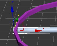
Then from the modifier section I selected the lathe tool from the modifiers and then applied the lathe to the full 360 degrees and created the shape below.
Wednesday, 26 October 2011
Sunday, 16 October 2011
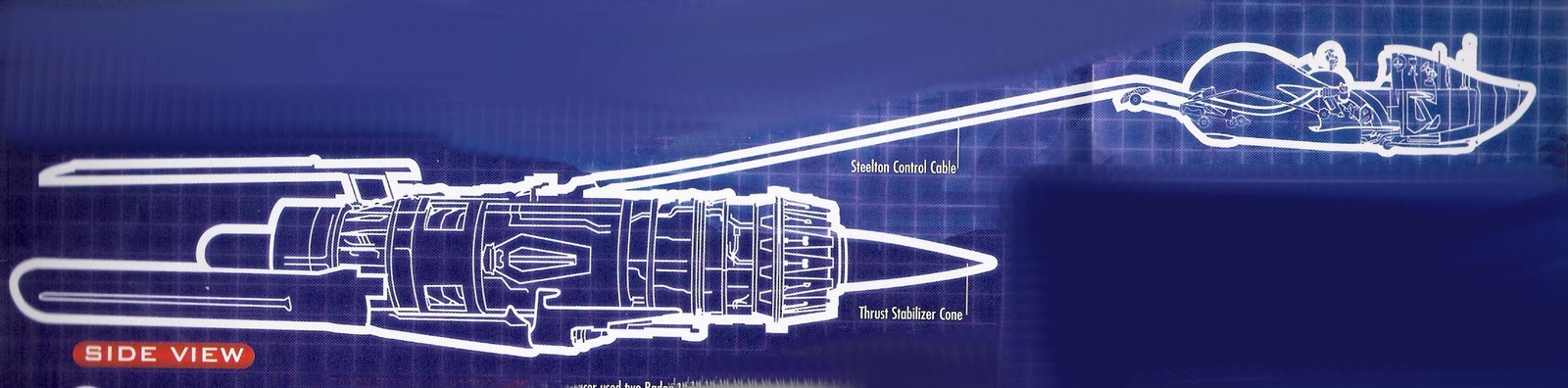
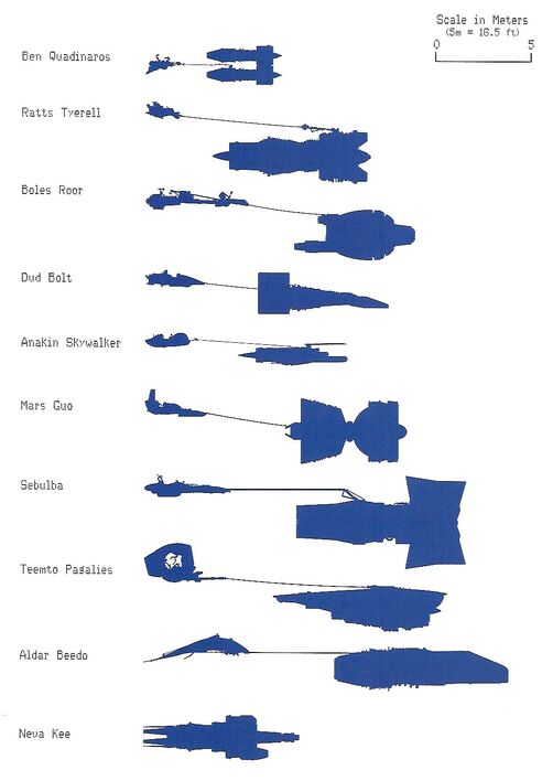
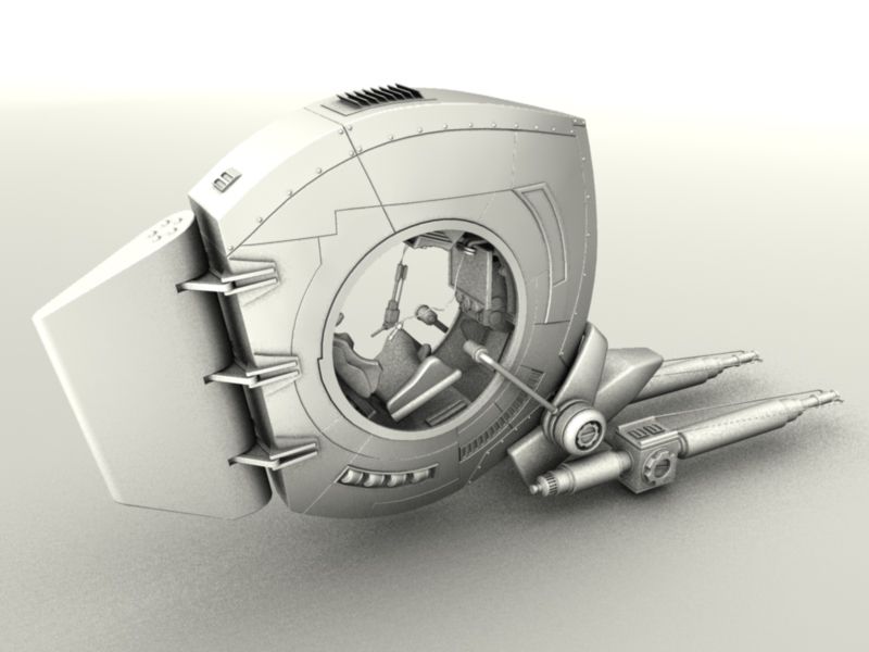
Pod Racing images & inspiration
http://images1.wikia.nocookie.net/__cb20071013180017/starwars/images/thumb/9/9c/Podracers1_negvv.jpg/492px-Podracers1_negvv.jpg
http://images.wikia.com/starwars/images/6/6e/Anipod_negvv.jpg
http://downloads.khinsider.com/wallpaper/1024x768/2471-pod-racer-002-zdczt.jpg
http://www.wallpaperpimper.com/wallpaper/Games/Pod_Racer/Pod-Racer-4-1024x768.jpg
http://img.photobucket.com/albums/v605/frostee3000/teemto_pagalies_pod_racer_cockpit03.jpg
http://www.smcars.net/forums/attachments/star-wars/38174d1145947237-anakins-pod-racer-anakin-side-view.jpg
http://www.smcars.net/forums/attachments/star-wars/38173d1145947212-anakins-pod-racer-anakin-front-view.jpg
Mood boards
Below are 2 mood boards for my project. The first is to get a feel for the sort of terrain and environment that my Pod Race scene might be held in.
The second board is to get a feel for the power, competitiveness and racing elements of my scene.
Building a castle
For this task we had to build a castle within 3D max. It was to have full battlements and a door in to the castle.
During this project I used two new tools firstly the Align Tool and secondly the Boolean removal tool.
To start off I created a cylinder and a cone after this I went in to the parameters for each object and gave them the same diameter, this meant that when I came to align them they would look good together with no overhang or rough edges.
The following 2 images show the creation of the 2 objects.
Once the two objects had been created and sized it was time to align them. The below image is a shot of the tool bar where the align tool is located.
To align two objects you first select the object you wish to move. You then click the align button on the toolbar and then select the object you with to align with.
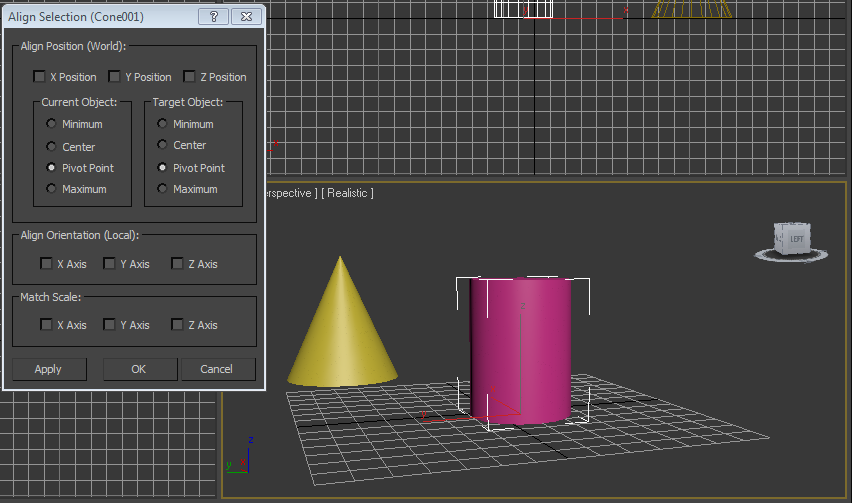
So now with the align window open we have some options for getting the objects where we want them. you are able to alight your objects on any axis you wish and you are also able to line the objects on whichever edge you wish.
First I aligned the objects on the X & Y axis so that they were positioned in the same place with the same centre.
The next stage was to align the maximum (top) of my cylinder with the minimum (bottom) of my cone and then accept.
With hindsight I realised that I went about aligning my objects the wrong way. If I had aligned the cone to my cylinder this would have created slightly less work for myself as once I had aligned the 2 objects I then had to group and move the grouped object up together on the x axis.
Once I had created my towers I grouped them together and cloned them so I had 4 towers I then placed these an equal distance apart in the corners of the grid.
The next step was to create the castle walls this was fairly straight forward as I just drew a box and fine adjusted it to contact 2 towers and then cloned and rotated it 90 degrees each time to create the 4 wall's.
This is how my castle looked after the walls had been built.
The next stage was to make the walls look a bit more like a castle and add some battlements.
The way I did this was with another new tool called boolean. What this allows you to do is create a shape and then position it into another and then cut that shape out.
Firstly you have to select one object and position it to the section you would like removed and then from the compound objects drop down select and Boolean.
From here you are now able to decide which object you would like to remove from the other this is done by selecting subtraction and A from B or B from A you then select which item you would like to be B and the section is removed leaving clean sealed lines on your shape.
I created a box which I repetitvly cloned and positioned along my walls and then Boolean removed each of the boxes in turn.
To change my cutting tool for my walls I simply rotated it 90 degrees so i could then move down the next wall
The Boolean process in action.
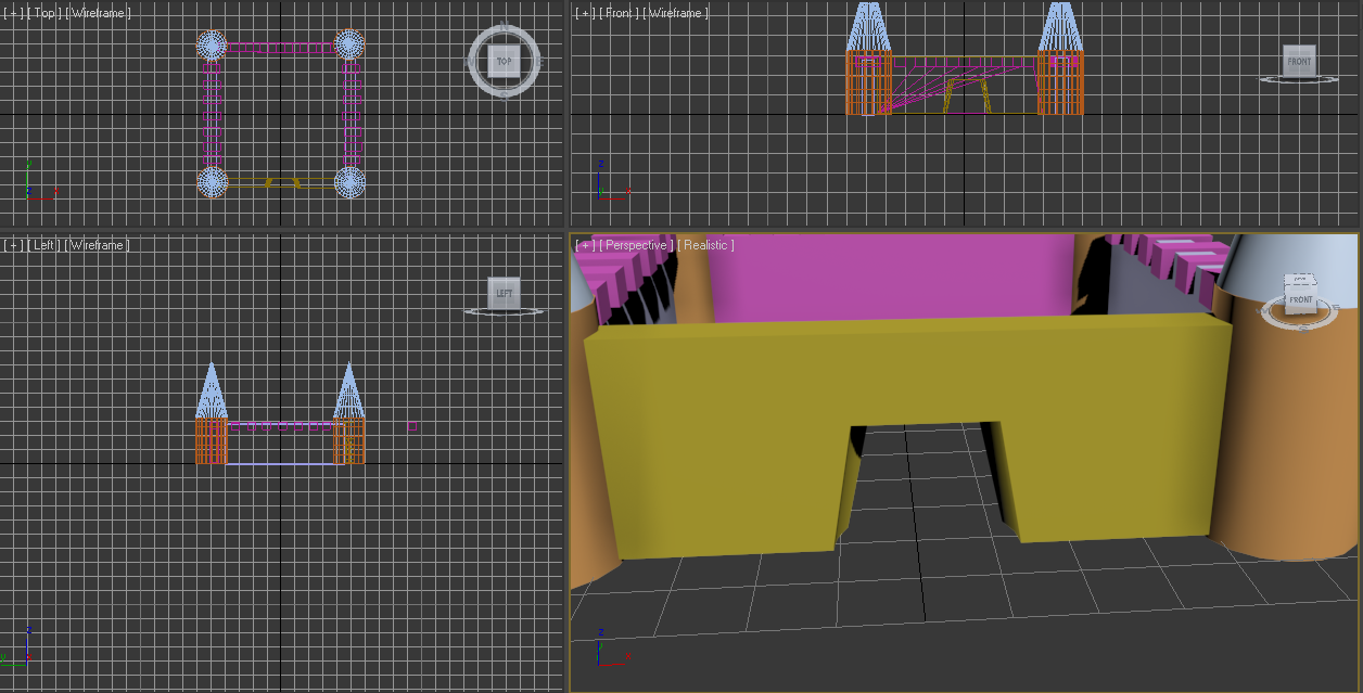
The next thing I did was cut the door out of the front of the castle this was done once again with the boolean tool but I made a nice door shape using a cone and inverting it. this gave the door the nice inward curve I was looking for
I also added some extra sections to my castle once again I used Boolean firstly to cut a smaller box out of another and then to give it more of a battlement feel.
I then cloned the extra battlements so there could be one on each side.
And this is my finished castle.
Saving in 3d Max
When working in 3D Max it is important to save your work as you go along. This is mainly because it is very easy to ruin a good piece of work with a couple of mistakes and sometimes the undo function can't save you.
Autodesk have included a nice feature within the save as menu that allows you to create easy progressive backups quickly and efficiently.
Just to the left of the save button you will notice another button with + marked on it if you click this button the project will be saved but with its final number increased by one.
For example if your project is called Starwars if you press the button the next save will be starwars1 and so on.
Autodesk have included a nice feature within the save as menu that allows you to create easy progressive backups quickly and efficiently.
Just to the left of the save button you will notice another button with + marked on it if you click this button the project will be saved but with its final number increased by one.
For example if your project is called Starwars if you press the button the next save will be starwars1 and so on.
Little house on the polygon
The next task was to build a house and edit it at the polygon level.
The fist thing to do was to draw a box from the standard primitves on the right hand tool bar.
Next I selected the box and under the Parameters section I adjusted the Length & width segments to 8 each.
I was now able to select individual polygons and adjust them. The first thing I did was remove 2 4x4 polygon sections for the windows on the front and a 2x3 polygon section for the front door.
After this i looked at what the move tool could do to polygons at this level.
The move tool allows you to stretch polygons so that from your original shape you can push them in or pull them out to create curves and other shapes.
This will be very useful when it comes to my final project because my pod racers will have lots of areas where this is useful.
I finished off my house by adding another 4x4 pixel window to the side and then created an interesting roof which made it look like an old mill building from around the time of the industrial revolution.
The fist thing to do was to draw a box from the standard primitves on the right hand tool bar.
Next I selected the box and under the Parameters section I adjusted the Length & width segments to 8 each.
After this was done I changed the view in the viewport to Realistic + Edged faces so that the grid could be seen and then right clicked on the box and changed it to editable polygons.
My my view and box were now ready for some polygon minipulation.
The next step with the box selected was to select the polygon level from the modifier menu.
I was now able to select individual polygons and adjust them. The first thing I did was remove 2 4x4 polygon sections for the windows on the front and a 2x3 polygon section for the front door.
After this i looked at what the move tool could do to polygons at this level.
The move tool allows you to stretch polygons so that from your original shape you can push them in or pull them out to create curves and other shapes.
This will be very useful when it comes to my final project because my pod racers will have lots of areas where this is useful.
I finished off my house by adding another 4x4 pixel window to the side and then created an interesting roof which made it look like an old mill building from around the time of the industrial revolution.
Getting Started (re creating the "ships" wheel)
For our first task in 3D studio max we have to create a ships wheel.
Once the outer frame of the wheel was created it was time to create the inner beams of the wheel this was done by creating a cylinder narrow enough to fit within the frame but also long enough that it pertruded outside of the frame to create some handles. This was done by adjusting the height variable in the modifier section of the right hand tool window.
After the rotation I did some minor tweaking of the cylinders position. This is done with the move tool when you select this tool from the top tool bar you are presented with 3 axis arrows roughly forming a cube. These arrows allow you to move the object on one axis without affecting another.
When the object is selected it is also possible to hover between the axis arrows, when this is done a yellow box appears and if this is clicked you have completely free movement of the object.
Next I used the clone tool to create the 2 extra beams which would cross over the central beam.To clone an object I held down shift and then dragged a clone away on the Y axis this then prompted a input window asking me if I wanted to re-name my new object.
THe next stage was to use the rotate & move tools again to position the two cross beams.
Once this was completed I wanted to add the centre of the wheel this was done by drawing a cylinder and then looking at the other perspectives as I drew it this allowed me to see that it was level with the outer ring and the cross beams giving this final product.
To do this I started by using the tube tool which is located in the creation section of the right hand tool bar. Towards the bottom of the tool bar.
When you select the tube tool the parameters change at the bottom of the tool bar.
It now presents you with Radius1 which controls the size of the outer radius of the tube and radius1 which controls the inside and this allows you to control the thickness of the tube with a lot of precision.
The next step was to draw out the tube in the viewport by first dragging out the outer circle and then the inner circle this would then create the outer ring of my wheel.
Once the outer frame of the wheel was created it was time to create the inner beams of the wheel this was done by creating a cylinder narrow enough to fit within the frame but also long enough that it pertruded outside of the frame to create some handles. This was done by adjusting the height variable in the modifier section of the right hand tool window.
Once the cylinder had been drawn I then had to adjust its orientation and position. This was done using the rotate tool. First you select the object you would like to rotate and then select Rotate from the top toolbar.
You are then presented with a wireframe ball which is very much like a track ball. You then click on one of the axis and roll round to position your object. There is an easier way of doing this using the alignment tool which I will cover in a later post.
After the rotation I did some minor tweaking of the cylinders position. This is done with the move tool when you select this tool from the top tool bar you are presented with 3 axis arrows roughly forming a cube. These arrows allow you to move the object on one axis without affecting another.
When the object is selected it is also possible to hover between the axis arrows, when this is done a yellow box appears and if this is clicked you have completely free movement of the object.
Next I used the clone tool to create the 2 extra beams which would cross over the central beam.To clone an object I held down shift and then dragged a clone away on the Y axis this then prompted a input window asking me if I wanted to re-name my new object.
THe next stage was to use the rotate & move tools again to position the two cross beams.
Once this was completed I wanted to add the centre of the wheel this was done by drawing a cylinder and then looking at the other perspectives as I drew it this allowed me to see that it was level with the outer ring and the cross beams giving this final product.
Subscribe to:
Posts (Atom)